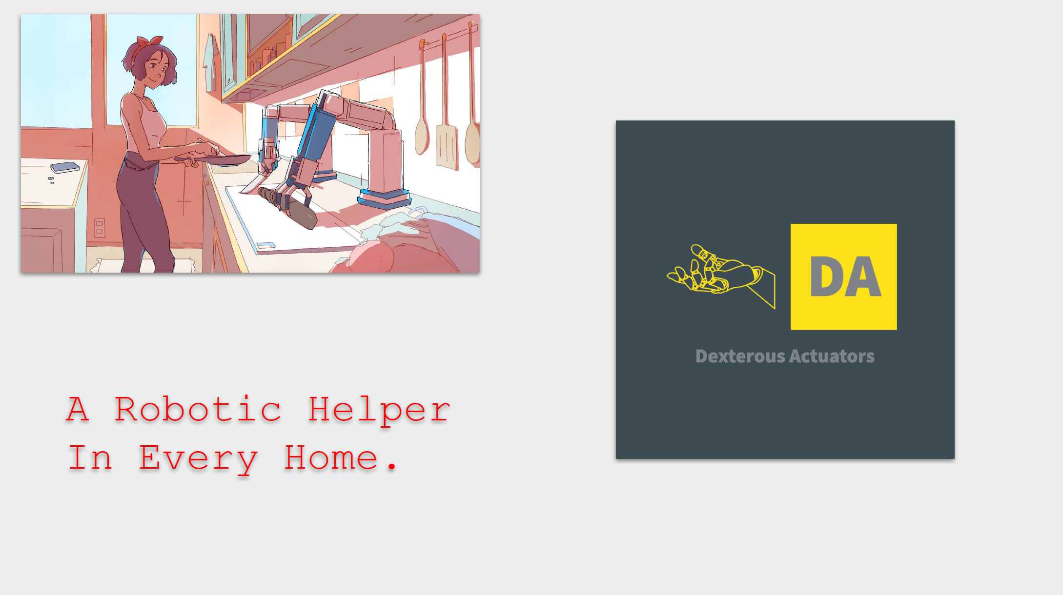
A Robotic Helper for Everyone, In Every Home.
We have all grown up watching sci-fi movies showing cool robots helping people in everyday scenes.
Yet, this dream appears to be always just out of reach.
We present a consumer robotic hand with the versatility of a human hand while being extremely affordable.
We will create an inexpensive consumer robotic aid for people to perform mundane tasks like cutting vegetables and putting away groceries in the home.
Contact us at: info@dexterousactuator.com
Demonstration Video (Click to Play)
Pitch Deck
Round, Funding and Financials
We are seeking seed level funding to bring to market a Robotic Aid for the disabled, as illustrated below:
[ ]
]
We are seeking to raise 1.5 million dollars for promise-of-equity of 33%. The detailed breakdown of how the money will be used is show in the Google sheet below:
![]()
 |
 |
Appendixes
The appendixes below provides some additional information for technical transparency and due-diligence.
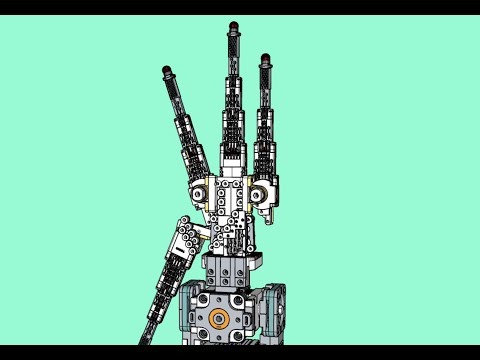
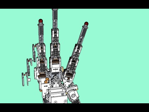
Appendix A: Exploded and Fly-Through Videos (Click to Play)
 |
 |
 |
Appendix B: List of Supported Grips
Cutkosky and Wright (1986b) studied various hand grasps used by technicians in a machine shop. Based on their observations they generated a taxonomy for human grips. They identified 16 grasps used in such a work environment.
We have listed these below and noted whether or not they can be performed by the robotic actuator (RA).
Terms:
- Prehensile: Grabbing with fingers.
- Non-prehensile: Involves no grabbing.
- Prismatic: Grabbing like a cylinder.
- Circular: Grabbing like a ball.
- Power: Grip formed by the inner surfaces of the fingers and palm.
- Precision: the grip is formed by the fingertips.
The illustrations of the graphs are taken from “Human Grasp Choices and Robotic Grasp Analysis” by Cutkosky and Howe. Copyright belongs to the original owner M. J. Dowling and Robotics Institute, Carnegie-Mellon University
| Grasp | Illustration | Type | Can it be performed by the Actuator? | RA Image |
|---|---|---|---|---|
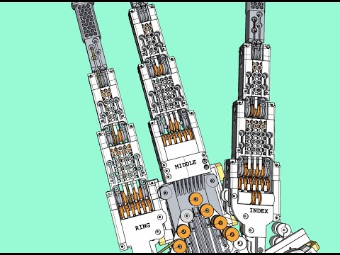
| Heavy Wrap - Large Diameter | 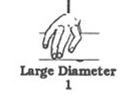 |
Power, Prehensile, Prismatic | Yes | 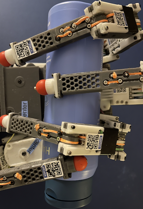 |
| Heavy Wrap - Small Diameter |  |
Power, Prehensile, Prismatic | No | |
| Medium Wrap |  |
Power, Prehensile, Prismatic | No | |
| Abducted Thumb |  |
Power, Prehensile, Prismatic | No | |
| Light Tool |  |
Power, Prehensile, Prismatic | Yes | 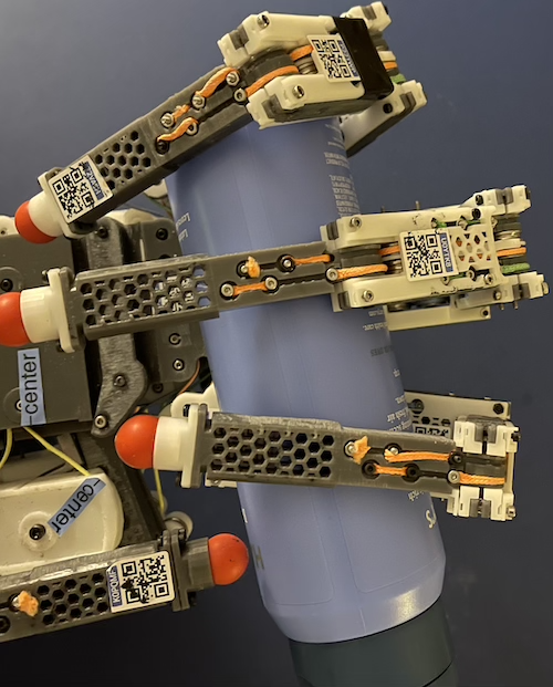 |
| Thumb-4 Finger |  |
Precision, Prismatic | No | |
| Thumb-3 Finger |  |
Precision, Prismatic | No | |
| Thumb-2 Finger |  |
Precision, Prismatic | Yes |  |
| Thumb-Index Finger |  |
Precision, Prismatic | Yes |  |
| Power-Disk |  |
Power, Circular | Yes |  |
| Power Sphere |  |
Power, Circular | Yes | Same as Power-Disk, except with more flex on the end joint. |
| Precision Disk |  |
Precision, Circular | Yes |  |
| Precision Sphere |  |
Precision, Circular | Yes | Similar to Precision disk, but joints are more closed. |
| Tripod |  |
Precision, Circular | Yes |  |
| Platform |  |
Power, Non-Prehensile | Yes |  |
| Lateral Pinch |  |
Power, Prehensile, Prismatic | No |
Appendix C: Prototype Motor Controller
For the robotic actuator to perform grips, we need to power the 17 motors in the arm in a coordinated manner.
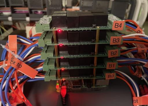
To enable this we built a programmable motor controller which can control up to 32 electric motors.
We have provided the details of the contruction and programming of this device in this wiki on Github:

Appendix D: Solution To The QR-Code Based Optical Configuration Detection Problem.
Optical configuration detection consists of three steps:
- Detecting all the observable QR codes in a video frame.
- Calculating the position of each QR code in the World coordinate system.
- Solving for the joint flex angles of the hand, using position of the QR codes obtained in step 2.
Step 1 There are cloud services that use Machine Learning models to accomplish rapid and accurate detection of QR codes in a video feed. The output of these will be the bounding box of each QR code detected in the video frame.

Step 2 is achieved by solving the Camera Equation below, using the results of Step 1.

where:
(u, v)is the location of the QR code in the video frame.f_x,f_yare the focal lengths of the camera.u_0andv_0and camera distortion parameters which can be obtained by the manufacturer.sis a scaling factor in the image, which would be known, form the camera zoom setting.- The
[r_ij]matrix is the camera’s rotation matrix and(t_i)vector is the camera’s translation vector from the World coordinate system’s origin. These can be measured directly. If the camera is fixed on the workbench, these will be static. (x,y,z)are the coordinates of the QR code in the world coordinate system. Solving this equation will yield a line in the World coordinate system. The line will pass through the camera.
The location of the QR code on this line can be obtained by calculating the distance of the QR code from the camera. This distance can be obtained by comparing the apparent width of the QR code in the image against the actual width, which is known.
Step 3: Once the location of a sufficient number of QR codes are obtained, we can solve for the configuration of the hand as follows.

Let’s say we are trying to figure out the configuration of the index finger.
With reference to the figure above, this configuration is fully described by:
- The rotation of the wrist around to the y-axis in the world coordinate system:
THETA_wrist, - The rotation of the wrist around to the x-axis in the world coordinate system: ‘PHI_wrist`,
- How much the finger has spread out form the straight position:
THETA_index_rot - The flex of the first joint of the index finger. This is the joint that connects it to the palm.
THETA_index_base - The flex of the middle joint, from the straight position relative to the previous segment. When the middle segment is parallel to the base segment this angle is zero.:
THETA_index_middle: - The flex of joint closest to the tip:
THETA_index_tip
To fully describe the configuration of the index finger, we need to solve for these six angles.
Now let us derive the positions of all the QR codes - whose locations are known in the World coordinate system - in terms of the angles and vectors described above.
For simplicity, let’s assume the QR codes are located at the following locations:
- The QR code at the center of the wrist:
Q_wrist - The QR code at the point where the palm meets the finger, around which it rotates when spreading in and out:
Q_index_rot - The QR code at the base joint of the index finger:
Q_index_base - The QR code where the base segment meets the middle segment:
Q_index_middle - The QR code at where the middle segment meets the tip segment:
Q_index_tip - The QR code at the end of the tip segment:
Q_index_end
Additionally the following 5 quantities are known from the dimensions of the hand.
- The vector from the center of the wrist
Q_wristto the center of rotation of the spread motionQ_index_rot:R^prime _wrist_to_rot - The vector from the center of rotation of the spread motion
Q_index_rot, to the point to the base jointQ_index_base:R^prime _rot_to_base - The length of the first base segment:
|R_base_to_middle| - The length of the middle finger segment:
|R_middle_to_tip| - The length of the tip finger segment:
|R_tip to end|
Now we form the following equations which establishes a relationship between the above known quantities and the 6 unknown angles we need to solve for.
Here R(PHI, THETA, RHO) is the rotation matrix that will rotate any vector around the x axis by PHI , around the y axis by THETA and around the z axis by RHO.

As we have six equations with six scalar unknowns, the above equations will yield the configuration of the wrist and the index fingers.
These can be solved using one of many numerical linear algebra libraries that are available.